UML fully known as Unified Modeling Language is a tool utilised in software development. Several UML diagrams serve different purposes but the entire idea of a UML is to express information or knowledge or systems in a standard and defined that aids the interpretation of the structure. They are standard terms and diagrams that are rich enough to enable developers to specify, construct and document the look of a system. Use cases are really useful in the development of a good product.
Use case diagrams
A use case diagram is an example of a behavioural diagram in UML that depicts dynamic relationships between the system and the users. It represents the functional requirements of a system.
This diagram illustrates the activities performed by the users of the system and describes the functionality of the system in terms of actors, use cases and the relationships between these use cases. It is a way of representing the way a system interacts with the users.
Use case diagrams are simple and only contain a few shapes. Use cases help to design a system from the end-users perspective.
How Important are Use Case Modeling
- Use case diagrams provide a structure for gathering customer requirements and setting the project scope.
- The diagrams are part of tools important in system validation.
- They are also useful in product testing. While they do not provide complete information for the development of the testing plan; they are especially important in developing the users' test to formulate acceptance test scenarios.
- Use cases help to link business and product vision and objectives.
- Use cases provide succinct information required by stakeholders.
Key Concepts of the Use Case Diagram
- It simply specifies the use cases (system behaviour).
- It summarizes some of the relationships between the use cases, actors and the system.
- It shows processes in consideration.
It models the basic flow of events in a use case.
It does not show the order of steps performed to achieve the goals of each use case.
Elements of the Use Case Diagrams
System
Actors
Use cases
Relationships

SYSTEM
The system is described as the subject/product to be created. It is the boundary of the subject/product. This defines the entire system as defined in the product requirement document.
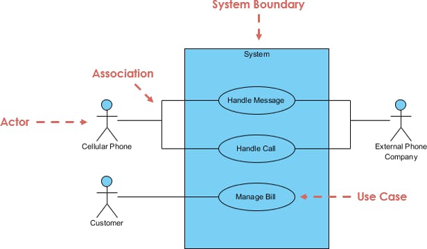
Use cases are enclosed within a subject boundary and this subject boundary helps to define the scope of the system. It specifies which part of the diagram is external and internal to it. For example, the boundaries of a mobile communication system will include the entire application and its interface. The customers and the phone company will be external to it as they use the system.
Determination of the system scope is a foundation for product management and also helpful in the elucidation of actors.

ACTORS
An actor is not a specific user but a user's role while interacting with the system. An actor plays a role in the system and a user can play different roles.
Actors are external entities that interact directly with the system. They trigger use cases and can generally provide inputs for the system, receive outputs from the system or do both.
Actors can also represent another system in which the current system interacts. This shows that Actors have a very wide scope of entities and can be people, things, institutions, time, other systems, etc.
These entities are described not by their titles but by the roles they play. The Actors are the cellular phone, the phone company, and the users of the mobile communication system. They are named by a noun in the diagram.

USE CASE
Use cases describe the process that occurs within a system. They are named with an active verb and a noun. They initiate the system to do something.
A use case is depicted by an oval in the UML. An actor must be linked to a use case but some use cases are not linked to actors.
The participation is an actor in a use case is shown by connections. These connections are known as Association.

ASSOCIATION
Use cases are connected to actors through association relationships. These relationships show how the use cases and actors interact.
Use cases share different kinds of relationship and associations can also be used to show relationships between use cases.
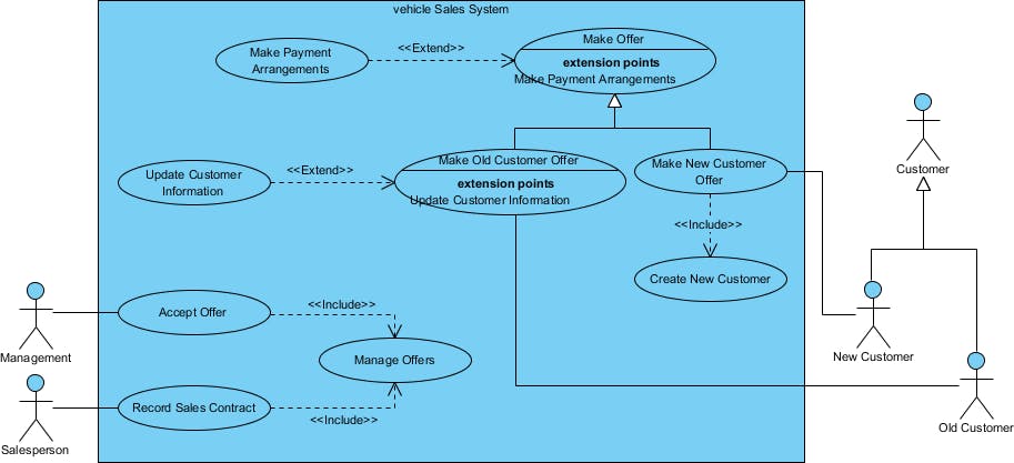
Associations can be "extend" which denotes additional functionality, "include" which denotes a shared use case and "generalization" which denotes that a use case inherits the behaviour of a parent use case.

Constructing a Use Case Diagram
Review the requirements definition.
This helps to obtain a complete overview of the process being modeled.
Identify System's boundaries.
This helps the product manager to identify the scope of the system.
Identify the Primary Actors and their goals.
Identify all system users, Identify all roles played by the users relevant to the system and the goals which include the system functionalities required by the actors to perform these roles. This describes the course taken to reach the goal. Use cases can be created for every goal.
Identify the Business Processes and Major use cases.
Identifying the major use cases first is a good way to start. This prevents the omission of any major use cases. This process of identification is iterative and is subject to stakeholders changing opinions and inclusions.
Extend Use cases
Consider every alternative course of events and extend the use cases.
Design packages for logical categorization of related subsystems.
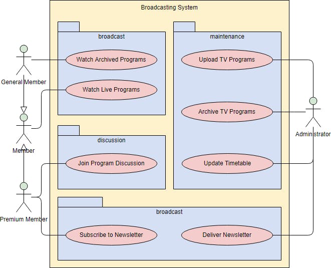
This can be utilized when more than 9 uses cases exists. The use cases are grouped into packages to make the diagrams easier to read and keep the models at a reasonable level of complexity.

Successfully review the current set of Use cases.
The inclusions of use cases are defined and even new use cases are identified. The use cases should have optimal inclusions to accommodate the size of the system.
Developing use case diagrams can seem a bit tasking but they possess great benefit as they serve as a simplified view of the system really important in analysis and planning in product development.
